



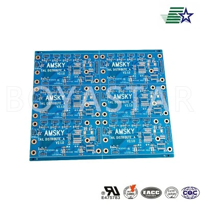

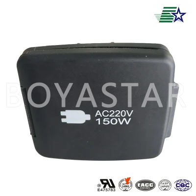
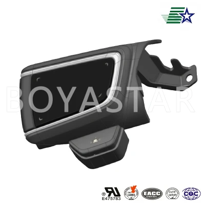
What are the common problems with equipment PCBs?
Nov 03, 2026
Leave a message
If you’re in the market for reliable electronic components that keep industrial and commercial equipment running smoothly, you know the critical role that Equipment PCB play in nearly every machine on the production floor, in medical devices, in renewable energy systems, and beyond. As a supplier who’s worked with these boards for over a decade, I’ve seen firsthand how even the smallest flaw in a printed circuit board (PCB) can bring an entire operation to a halt, leading to costly downtime, lost revenue, and frustrated clients. Today, I want to break down the most common problems with Equipment PCBs, share what I’ve learned from helping hundreds of clients troubleshoot these issues, and explain how partnering with an experienced supplier can help you avoid these pitfalls.
First, let’s set the stage: Equipment PCBs aren’t the same as consumer PCBs for phones or laptops. They’re built to withstand harsh environments—extreme temperatures, vibration, dust, humidity, and constant use—so their design, materials, and manufacturing quality have to be far more robust. That’s why our team at AB focuses specifically on high-grade, application-specific PCBs, from heavy-duty Industrial Drive PCB that power conveyor belts and factory automation, to specialized boards for medical diagnostic equipment and energy systems. Even with that focus, though, issues can pop up, either during manufacturing, installation, or years of operation.
The most frequent problem I encounter is related to poor solder joint quality. Solder joints are the tiny connections that link the PCB to its components, and they’re the weakest point on most Equipment PCBs. Why? Because they’re exposed to thermal cycling—when a machine heats up during use and cools down when it’s turned off, the solder expands and contracts at a different rate than the PCB material. Over time, this repeated stress can cause “cold joints” (where the solder didn’t flow properly to create a strong bond), “solder cracking,” or even “solder bridging” (where excess solder connects two adjacent pins, causing a short circuit). Last year, a client who builds small industrial pump systems came to me with a batch of pumps that were failing within three months of installation. The issue? Cold solder joints on the pressure sensor PCBs, which would crack when the pump vibrated during operation. We reworked the boards with controlled reflow soldering and improved component placement, and their failure rate dropped by 90%. That’s the kind of real-world impact solder joint issues can have.
Another common headache is incorrect material selection. Equipment PCBs need materials that match their intended application, and cutting corners here leads to big problems. For example, if you use a standard FR-4 PCB for a high-temperature industrial furnace controller, the material will degrade over time, causing the board to warp, delaminate (where the layers of the PCB separate), or lose electrical conductivity. I’ve also seen clients try to use general-purpose PCBs for New Energy Vehicle PCB systems, which require high thermal resistance and vibration resistance to handle the demands of electric drivetrains. One of our automotive clients once shared that a competitor’s “budget” PCB for their battery management system was failing because it couldn’t handle the thermal cycling from charging and discharging, leading to inconsistent performance. At AB, we work closely with clients to select materials tailored to their use case—whether that’s high-Tg FR-4 for extreme temperatures, aluminum-based PCBs for better heat dissipation, or specialized epoxy resins for heavy vibration applications. That’s why our Equipment PCB offerings are designed to meet specific performance standards, not just generic specifications.
Design flaws are third on the list of common Equipment PCB problems, and many of these can be traced back to not accounting for real-world use. A classic example is improper trace routing. Traces are the thin copper lines that carry electrical signals across the PCB. If they’re too narrow, they can overheat and break under high current loads; if they’re too close together, signal interference (crosstalk) can occur, leading to erratic machine operation. I also see issues with inadequate clearance between high-voltage traces and low-voltage circuits, which can cause arcing in humid or dusty environments. Last year, a medical device manufacturer brought us a PCB for a blood analyzer that was giving false readings. The problem? The design team had routed the signal traces too close to the power traces, and electrical interference was corrupting the sensor data. We adjusted the trace spacing, added shielding layers, and the analyzer’s accuracy returned to 99.9%—a fix that would’ve been impossible to implement after manufacturing if we hadn’t caught the design flaw early. For clients building Main Control PCB systems, which are the “brain” of entire equipment lines, design rigor is non-negotiable; even small oversights can cascade into massive operational failures.

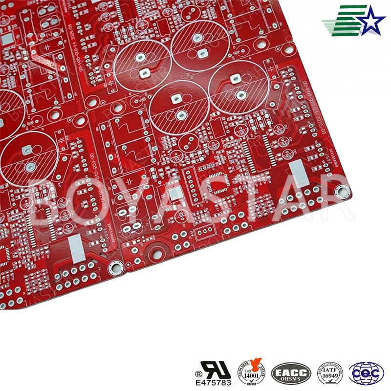
Moisture and corrosion damage is another frequent issue, especially for Equipment PCBs used outdoors, in coastal areas, or in industries like food and beverage where washing and high humidity are regular occurrences. When moisture seeps into the PCB’s layers, it can cause copper traces to corrode, leading to open circuits, or create shorts between adjacent traces. I worked with a client that builds agricultural irrigation control systems, which are installed in fields exposed to rain, dust, and fertilizer chemicals. Their original PCBs were not coated, and after one rainy season, 20% of the units had failed due to corrosion. We recommended applying a conformal coating—a thin, protective layer of polymer that seals the PCB without interfering with performance—and that problem was completely resolved. Conformal coatings aren’t a one-size-fits-all solution, though; some require UV resistance, others chemical resistance, and our team helps clients choose the right coating for their specific operating environment.
Quality control gaps during manufacturing also contribute to Equipment PCB problems, and this is an area where not all suppliers are created equal. Even if the design and materials are perfect, a small oversight in production can ruin a board. For example, improper etching can leave residual copper where it shouldn’t be, causing shorts; inadequate soldering can leave weak joints, as I mentioned earlier; or inconsistent layer alignment can create signal integrity issues. At AB, we have a multi-step quality control process that includes automated optical inspection (AOI), X-ray inspection for hidden solder joints, and functional testing for every batch of Equipment PCBs. We once had a client switch to us from a lower-cost supplier because they were receiving PCBs with hidden voids in solder joints—voids that didn’t show up in visual inspection but would cause intermittent failures during operation. Our X-ray process caught these voids before shipment, eliminating the client’s ongoing maintenance costs.
Extreme thermal management issues round out the most common problems, and they’re especially critical for high-power Equipment PCBs, like those used in industrial drives or power inverters. If a PCB can’t dissipate heat properly, components will overheat, degrade faster, and fail prematurely. I’ve seen PCBs where the heat from a large power transistor built up too quickly, melting the solder joint and taking the entire machine offline. Solutions here range from adding larger copper traces and heat sinks to using high-thermal-conductivity materials like aluminum or ceramic substrates. For our Industrial Drive PCB clients, we often integrate thermal vias—small holes in the PCB that carry heat away from components to the outer layers—so the board can handle the constant high current without overheating.
Now, if you’re reading this, you might be wondering how to avoid these issues and ensure your Equipment PCBs are reliable. The answer starts with partnering with a supplier who understands these common pitfalls and prioritizes quality, not just low prices. At AB, we specialize in application-specific PCBs across industries, from the rugged Automotive PCB systems that power passenger and commercial EVs to the high-precision boards for medical and industrial equipment. We work closely with every client from the initial design phase through manufacturing, testing, and delivery to address potential issues before they become costly problems.
If you’re dealing with recurring PCB failures, looking to upgrade your current board design, or need a reliable supplier for your next batch of Equipment PCBs, we’re here to help. Contact our team today to discuss your specific needs, review your current PCB challenges, and explore solutions tailored to your equipment. Together, we can ensure your machines run smoothly, downtime is minimized, and your operations stay on track.
- Electronic Design. (2022). Common PCB Failure Modes and How to Prevent Them. Retrieved from https://www.electronicdesign.com/pcb-design/article/21804807/common-pcb-failure-modes-and-how-to-prevent-them
- IPC Association Connecting Electronics Industries. (2021). Design Guide for Printed Circuit Boards for Industrial Equipment. Retrieved from https://www.ipc.org/ContentPage.aspx?area=Standards&nodeid=468
- NASA Goddard Space Flight Center. (2020). PCB Environmental Stress and Failure Analysis. Retrieved from https://nepp.nasa.gov/Documents/PCB_Stress_Analysis.pdf
- Soldertec. (2019. Solder Joint Quality: Causes of Failure and Testing Methods. Retrieved from https://www.soldertec.org/publications/whitepapers/solder-joint-quality-failure-causes-testing/
- Conformal Coating Association. (2022. Conformal Coating Selection for Harsh Environment PCBs. Retrieved from https://conformalcoating.org/resources/selection-guide/
Send Inquiry