




Main configuration of equipment power PCB board
Aug 13, 2026
Leave a message
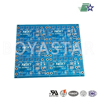
The substrate and board structure are the most fundamental core configurations of equipment power PCB, directly determining the insulation performance, heat dissipation capacity, and structural stability of the circuit board. Industrial equipment power supplies commonly use FR-4 high-quality epoxy glass cloth substrates, and some high-power and high-temperature equipment will use high TG heat-resistant sheets to effectively avoid softening and delamination deformation of the sheets caused by long-term high-temperature work. The thickness of the board is matched with standard specifications such as 1.6mm and 2.0mm according to the power supply, ensuring sufficient rigidity of the board surface and capable of carrying heavy-duty components such as transformers, electrolytic capacitors, and power tubes. At the same time, the substrate has the characteristics of high insulation, low water absorption, and aging resistance, which can adapt to complex indoor and outdoor temperature and humidity environments. From the hardware material perspective, it ensures the long-term stable operation of the power circuit and eliminates basic problems such as leakage and insulation failure.
The thickness of copper foil and the current carrying configuration of the circuit are key configurations for adapting to the high-power and high current working characteristics of equipment power supply. Different from the thin copper design of ordinary signal boards, the power PCB will be matched with a special thick copper foil according to the rated power and operating current. Typically, 1OZ to 3OZ thick copper layers are used, while high-power industrial power supplies will use thicker copper foil technology. The high-voltage main circuit, rectifier circuit, and output power supply circuit are all designed with widened wiring, greatly improving the current carrying capacity of the circuit, reducing the internal resistance of the circuit, and minimizing heating and voltage drop losses during power on. In terms of wiring configuration, strict differentiation is made between high-voltage and high-voltage areas and low-voltage signal areas. Independent wiring and isolation layout are carried out in different zones, and a dedicated grounding wiring system is used to meet the requirements of high current transmission and avoid problems such as line interference and short circuits. It is suitable for continuous full load operation of equipment.
Further improve the practicality and reliability of the equipment power PCB by configuring functional processes and auxiliary structures. The core power area of the board will be extensively covered with copper, with reserved heat dissipation windows and holes to facilitate the installation of heat dissipation fins and thermal pads, and quickly dissipate the heat generated by the operation of power devices. The surface process uniformly adopts the spray tin process with strong oxidation resistance and welding resistance. High end precision power supplies will use the immersion gold process to ensure that the solder joints are full, firm, and not easily oxidized or aged. At the same time, the board is equipped with standardized silk screen markings, positioning holes, and fixed installation holes. The structural layout conforms to the overall assembly dimensions of the equipment, and is designed with foolproof layout to avoid assembly errors. Some industrial control power supply PCBs will also add process configurations such as solder mask thickening and moisture-proof coating to enhance the board's resistance to moisture and corrosion, and fully adapt to the long-term continuous operation needs of industrial equipment.
Send Inquiry